


Small knowledge of parallel connection of diesel generator set
2021-10-05
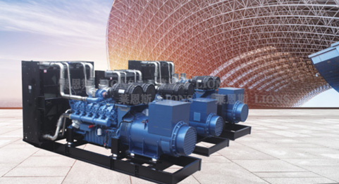
The parallel operation of two or more generator units can meet the demand of load change and greatly reduce the operation cost of generator units. Therefore, there is more and more demand for parallel connection of generator units in the market. Today, Raines will explain the basic knowledge of parallel machine:
1、 What are the conditions for parallel operation of generator sets?
The whole process of putting the generator set into parallel operation is called parallel operation. One generator set shall be operated first and the voltage shall be sent to the bus. After the other generator set is started, it shall be in parallel with the previous generator set. At the moment of closing, the generator set shall not have harmful impulse current and the rotating shaft shall not be suddenly impacted. After closing, the rotor shall be quickly pulled into synchronization. (i.e. the rotor speed is equal to the rated speed) therefore, the paralleling of generator sets must meet the following conditions:
The effective value and waveform of generator set voltage must be the same;
The voltage phases of the two generators are the same;
The frequency of the two generator sets is the same;
The phase sequence of the two generator sets is consistent.
2、 What is the quasi synchronous parallel method of generator set? How to make simultaneous juxtaposition?
Quasi synchronization is the exact period. For parallel operation with quasi synchronization method, the generator unit must have the same voltage, frequency and phase, which can be monitored by two voltmeters, two frequency meters, synchronization meters and non synchronization indicator lights installed on the synchronization panel. The parallel operation steps are as follows:
Close the load switch of one generator set and send the voltage to the bus, while the other unit is in standby state. Close the beginning of synchronization, adjust the speed of the generator set to be combined to make it equal to or close to the synchronous speed (the frequency difference with another unit is within half a cycle), and adjust the voltage of the generator set to be combined to make it close to the voltage of another generator set. When the frequency and voltage are similar, the rotation speed of the synchronization meter is slower and slower, and the synchronization indicator light is on and off.
When the phase of the unit to be combined is the same as that of another unit, the pointer of the synchronization meter indicates the middle position upward, and the synchronization lamp is the darkest. When the phase difference between the unit to be combined and the other unit is the largest, the synchronization meter points to the middle position downward, and the synchronization lamp is the brightest. When the pointer of the synchronization meter rotates clockwise, it indicates that the frequency of the generator to be combined is higher than that of the other unit, The speed of the generator set to be paralleled shall be reduced. On the contrary, when the pointer of the synchronous meter rotates counterclockwise, the speed of the generator set to be paralleled shall be increased.
When the pointer of the synchronization meter rotates slowly clockwise and the pointer approaches the synchronization point, close the circuit breaker of the unit to be paralleled immediately to make the two generator units parallel. Cut off the synchronization meter switch and relevant synchronization switches after parallel operation.
3、 What should be paid attention to during quasi synchronous paralleling of generator units?
Quasi synchronous paralleling is manual operation. Whether the operation is smooth or not has a great relationship with the experience of operators. In order to prevent asynchronous paralleling, the following three situations are not allowed to be closed.
1. When the pointer of the synchronous meter jumps, it is not allowed to switch on, because there may be tape jamming in the synchronous meter, which can not reflect the correct parallel conditions.
2. When the synchronization meter rotates too fast, it indicates that the frequency difference between the generator set to be combined and another generator set is too large. Because the closing time of the circuit breaker is difficult to grasp, the circuit breaker is often not closed at the synchronization point, so it is not allowed to close at this time.
3. If the pointer of the synchronous meter stops at the synchronous point, it is not allowed to close at the dead time. This is because if the frequency of one generator unit changes suddenly during the closing process of the circuit breaker, it may make the circuit breaker close at the non synchronous point.
4、 How to adjust the reverse power phenomenon of parallel units?
When two generator units are paralleled without load, there will be a problem of frequency difference and voltage difference between the two units. The monitoring instruments (ammeter, power meter and power factor meter) of the two units reflect the actual reverse work. One is the reverse work caused by inconsistent speed (frequency) and the other is the reverse work caused by unequal voltage. The adjustment is as follows:
1. Adjustment of reverse work caused by frequency: if the frequencies of two units are different and the difference is large, it is displayed on the instrument (ammeter and power meter). The current of the unit with high speed displays positive value and the power meter indicates positive power. On the contrary, the current indicates negative value and the power indicates negative value. At this time, adjust the speed (frequency) of one unit according to the indication of the power meter, and adjust the indication of the power meter to zero. Make the power indication of both units zero, so that the speed (frequency) of the two units is basically the same. However, when the ammeter still has indication, this is the reverse power phenomenon caused by voltage difference.
2. Adjustment of reverse work caused by voltage difference: when the indication of power meter of two units is zero and the ammeter still has current indication (i.e. one reverse and one positive indication), the voltage adjustment knob of one generator unit can be adjusted according to the indication of ammeter and power factor. Eliminate the indication of the ammeter (i.e. adjust it to zero). After the ammeter has no indication, the power factor can be adjusted to a lag of more than 0.5 according to the indication of the power factor meter. Generally, it can be adjusted to about 0.8, which is the best state.
5、 Generator protection circuit
1. Reverse power reverse power phenomenon is caused by the different speed (frequency) and voltage of generator set, that is, one generator set has positive power and the other unit has negative power. In other words, the unit with negative power becomes a load (the unit has low frequency and inconsistent speed). For units with different voltages and high voltage, provide a reactive current and reactive voltage (positive indication of ammeter of the unit) to units with low voltage, which is equivalent to adding a condenser group in the power supply system. At this time, the unit with low voltage becomes a large load and receives a large reactive current to maintain the voltage balance of the two units (the ammeter of this unit indicates in reverse). During monitoring, increase the voltage of one unit or the voltage of another unit, resulting in a unit having reverse power current, and its action current is about 20% of the rated current. The reverse power relay acts, trips and gives an alarm without shutdown.
2. Overcurrent: the current generator set has a certain rated power, and its overload capacity is very low, which is basically about 5% of the rated power. The allowable load time is 15 ~ 30 minutes, up to 60 minutes. Beyond this time, the generator set will heat up, the conductor insulation will be reduced, and the service life will be reduced. Therefore, if there are no special requirements when setting the overcurrent protection, the overcurrent protection can be set at 110% of the rated current. During load test, bring the current to 110% of the rated current, and the overcurrent relay acts. Trip, alarm and non shutdown.
3. Overvoltage: when the generator sets are used in parallel, the power supply system is most afraid of oscillation. Once oscillation occurs, the system voltage increases, which is easy to cause insulation breakdown of electrical equipment and power supply equipment, and paralyze the power supply equipment and electrical equipment together. Therefore, the generator sets used in parallel are equipped with overvoltage protection, and the best setting value is 105% of the rated voltage. Short circuit overvoltage relay, trip, shutdown and alarm action.